My Header Note
Welcome to Chengdu Sunshine Xihe Electric Co., Ltd
All Categories
Call us 24/7+86 18508516368

General info

This chapter describes standard cabinets that are available for Safety Manager systems.

Using standard cabinets provides several advantages over specifically designed cabinets. Honeywell SMS policy is aimed at delivering standard engineered, tested and certified (modular) concepts to the market for these main reasons:

Reusing existing concepts saves valuable time (e.g. engineering, testing, certification).

Individual projects will be delivered at a guaranteed level of quality and in short turn-around times.

Applying modularity within a proven overall concept provides for flexibility toward customers.

Typically, Safety Manager is installed in a standard cabinet. It is possible to add or rearrange certain components or change their location within the cabinet.

Also, standard Safety Manager remote cabinets are available. Depending on specific application needs one or more types can be opted for.HONEYWELL K2LCN-8 | 51401551-801 | Board | PLC Module
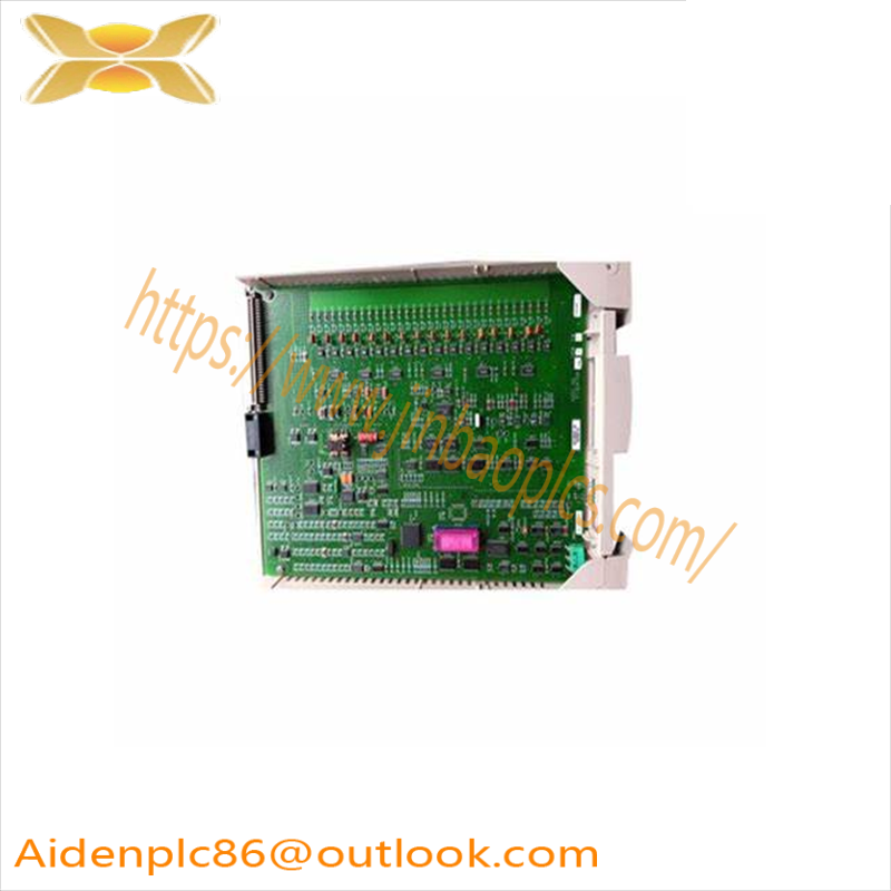
Should you not wish to follow the standard cabinet layout, then you can only do so after prior consult with Honeywell SMS.

Standard Rittal enclosure for Safety Manager

The standard enclosure for Safety Manager is based on two cabinet types available in the Rittal TS 8 series.

Safety Manager enclosures are default equipped with a swing frame, support glands, fans, an enclosure frame with steel doors, louvres and filters, an enclosure light, a thermostat, earthing strips, a mounting plate, gland plates, a rear panel and a roof or bottom plate. Side panels are mounted to the outer walls.

A standard Safety Manager enclosure is painted in RAL 7035, with RAL 7022 for the plinth.

Below sections provide more details related to the Rittal TS series as assembled and delivered by Honeywell SMS.

Enclosure light

The Rittal enclosure light (PS 4155.000) has an auto-select input voltage detector (110/230 V AC) and is equipped with a motion sensor. You no longer require an additional door switch. If the shipping section consists of more than one Rittal cabinet enclosure, all cabinets will have an enclosure light. All enclosure lights use the same feeder. The feeder is wired from the first cabinet (with an interconnection cable) to the second and, if applicable, from the second to the third cabinet, etc.

Fans

A pair of fans are mounted in the roof. The following types are available:

Papst, type 4184NX, operating voltage 24 V DC

Honeywell SMS fan unit which can be delivered in 3 voltages 24 V DC, 115 V AC, and one for 230 V AC. For a data sheet of the 24 V DC fan unit see FANWR-24R.

FANWR-24R (Preferred) 24Vdc fan unit with readback CC

51199947-275 FAN ASSEMBLY KIT 230VAC EC CC

51199947-175 Fan Assembly Kit, 115VAC, EC, CC

The Honeywell SMS fan units consist of a pair of fans. A read-back contact indicates the operational status of the fans.

Thermostat

The thermostat gives an alarm to alert you of temperature increasing inside the Safety Manager cabinet (e.g. when filters are blocked or fans fail). When a Honeywell SMS fan unit is installed, the thermostat is not required.

The Rittal SK 3110.000 thermostat is mounted on the top right-hand side of each Rittal cabinet and is suitable for temperatures ranging from +5°C-+55°C (+41°F-+131°F).

Fan unit 24 V DC with readback

The 24 V DC fan unit (FANWR-24R) consists of two fans and a printed circuit board (PCB) 07209 on a mounting plate.

The external 24 V DC power and readback contact wiring for the fan unit terminates on a 4 pole connector which slots into the fan unit.

Electronics in the fan unit generate the signals to indicate the fan status. If the speed of a fan is above minimum, a green LED next to that fan illuminates to indicate this. If both fans are above minimum speed the readback contact closes.

Finger guards are mounted on both sides of the fans.

The “Layout of the FANWR-24R fan unit and direction of air flow” below shows the direction of airflow and the bottom and side view of the fan unit.

Block diagram

The “Functional block diagram of the FANWR-24R fan unit” below shows a functional block diagram of the FANWR-24R fan unit.

Fan status indication

The fan unit is equipped with a potential free readback contact and green LEDs to indicate the fan status.

The readback contact is closed for about 15 seconds during powerup and when the rotation speed (RPM) of both fans is above the minimum speed.

A LED is on when the rotation speed (RPM) of the related fan is above the minimum speed.

Flow rate/Static pressure

The ” Flow rate against static pressure (per fan)” below shows the flow rate per fan against the static pressure. The grey area indicates the optimum operating range.

Electrical connections

The fan unit is equipped with a 4 pole screw connector to wire the readback contact and the 24Vdc power.

“Layout of the FANWR-24R fan unit and direction of air flow” on page 43 shows the location of the connector on the fan unit. The “The FANWR-24R fan unit connector details” on the facing page shows the connection details of this connector
Related product recommendations:
Rockwell Automation 1769-CLL1
ABB 3HAC14673-9 IRB6640/ 6600/6650/6650S
Allen Bradley 1756-IB16ISOE
ABB 1786-TCAP
ABB 3HAC022172-006
AB 1769-SDN/B 1769SDNB
1746-P6
Advanced 1771-OVN
ABB 3HAC055448-003
1771-HS1
Allen-Bradley 1757-SRM
ABB IRB 6640 3HAC8081-11
AdvancedTech 1336-BDB-SP49D
ABB IRB6700 Series 3HAC045143-003 
ABB DSQC406 3HAC035301-001/03
Allen-Bradley 1783-VS03T01F
More…

Product Specifications-3401

Analog Input Module

Each TMR Analog Input Module has three isolated sets of electronics, called channels, which independently process field data input to the module. Each channel places the processed data in an array and transmits this array, on request, to the MP associated with that channel. The MPs vote the data before passing it to the application. In TMR mode, the data passed is mid-value. In dual mode, the data passed is the average.

AI Modules include complete, ongoing diagnostics for each channel. If the diagnostics detect a failure on any channel, the Fault indicator turns on and activates the system alarm. The Fault indicator identifies a channel fault, not a complete module failure. AI Modules are guaranteed to operate properly in the presence of a single fault and may continue to operate properly with multiple faults.

AI Modules support a hot-spare module. Each AI Module is mechanically keyed to prevent improper installation in a configured baseplate.

The Model 3351 AI Module can be used with these baseplates:

• Model 2351, which is used in typical 4-20 mA applications.

• AI External Termination Baseplate,which is used with the Model 9764-510 RTD/TC/AI External Termination Panel or the Model 9792-310 AI Hazardous Location External Termination Panel.

• Model 2354, which is used in 4-20 mA applications and enables communication between HART field devices and Configuration and Asset Management Software running on a PC.

• Model 2354A, which is used in 4-20 mA applications in hazardous

locations and enables communication between HART field devices and Configuration and Asset Management Software running on a PC.

Analog Input/Digital Input Module

The Analog Input/Digital Input Module has 16 digital input points (points 1–16) and 16 analog input points (points 17– 32).

The AI/DI Module has three isolated sets of electronics, called channels, which independently process field data input to the module. Sensing of each input point is performed in a manner that prevents a single failure on one channel from affecting another channel.

For analog input points, each channel receives variable voltage signals from each point, converts them to digital values, and transmits the values to the three MPs on demand.

For digital input points, an ASIC on each channel scans each input point, compiles data, and transmits it to the MPs upon demand.

For all points, the MPs vote the data before passing it to the control program. In TMR mode, the data passed is midvalue. In dual mode, the data passed is the average.

AI/DI Modules sustain complete, ongoing diagnostics for each channel. If the diagnostics detect a failure on any channel, the Fault indicator turns on and activates the system alarm. The Fault indicator identifies a channel fault, not a complete module failure. AI/DI Modules are guaranteed to operate properly in the presence of a single fault and may continue to operate properly with multiple faults.

Analog Input/Digital Input Modules include the hot-spare feature which allows online replacement of a faulty module. The AI/DI Module is mechanically keyed to prevent improper installation in a configured baseplate.

The Model 3361 AI/DI Module is compatible with the Model 2361 AI/DI Baseplate and the AI/DI External Termination Baseplate.

Analog Output Modules

Each TMR Analog Output Module has three isolated sets of electronics, called channels, which independently accept data from the MP associated with each channel. The channels provide input to voter circuitry to select a single channel to drive the output. Special circuitry is used to ensure that the channels that are not driving the output are shunted so they cannot affect the output.

AO Modules include complete, ongoing diagnostics for each channel. If the diagnostics detect a failure on any channel, the Fault indicator turns on and activates the system alarm. The Fault indicator identifies a channel fault, not a complete module failure. AO Modules are guaranteed to operate properly in the presence of a single fault and may continue to operate properly with multiple faults.

AO Modules support a hot-spare module. Each AO Module is mechanically keyed to prevent improper installation in a configured baseplate.

The Model 3481 AO Module can be used with these baseplates:

• Model 2481, which is used in typical applications.

• Model 2483, which enables communication between HART field devices and Configuration and Asset Management Software running on a PC.

• Model 2483A, which is used in hazardous locations and enables communication between HART field devices and Configuration and Asset Management Software running on a PC.

• DO External Termination Baseplate, which is used with the Model 9863- 610 External Termination Panel in hazardous locations. Note that “DO” is not a typo, the DO External Termination Baseplate is used with the 9863-610.

The Model 3482 High-Current AO Module is compatible with only the Model 2481 Analog Output Baseplate.

Digital Input Module

Each TMR Digital Input Module has three isolated sets of electronics, called channels, which independently process field data to the module. Each channel places the processed data in an array and transmits this array, on request, to the MP associated with that channel. The MPs vote on the data before passing it to the application.

DI Modules include complete, ongoing diagnostics for each channel. If the diagnostics detect a failure on any channel, the Fault indicator turns on and activates the system alarm. The Fault indicator identifies a channel fault, not a complete module failure. The DI Module continuously verifies the ability of the system to detect transitions to the opposite state. DI Modules are guaranteed to operate properly in the presence of a single fault and may continue to operate properly with multiple faults.

DI Modules support a hot-spare module. Each DI Module is mechanically keyed to prevent improper installation in a configured baseplate.

The Model 3301 DI Module can be used with these baseplates:

• Model 2301, which is used with typical applications.

• DI External Termination Baseplate, which is used with the Solid State Relay Input External Termination Panel in high-voltage applications, or the Model 9573-610 DI Hazardous Location External Termination Panel.

Digital Output Module

Each TMR Digital Output Module has three isolated sets of electronics, called channels, which independently accept data from the MP associated with each channel. The channels use the patented Quad Voter circuitry to vote on individual output signals as they are applied to the load.

This voter circuitry is based on parallelseries paths which pass power if two out of three switches (channels A and B, or channels B and C, or channels A and C) command them to close. The Quad Voter circuitry has multiple redundancy on all critical signal paths, guaranteeing safety and maximum availability.

For each point, the DO Module periodically executes the Output Voter Diagnostic (OVD) routine. To allow unrestricted safe operation under a variety of multiple-fault scenarios, OVD detects and alarms these types of faults:

• Points—all stuck-on and stuck-offs are detected in less than 500 milliseconds.

• Switches—all stuck-on or stuck-off switches or their associated drive circuitry are detected.

DO Modules include complete, ongoing diagnostics for each channel. If the diagnostics detect a failure on any channel, the Fault indicator turns on and activates the system alarm. The Fault indicator identifies a channel fault, not a complete module failure. DO Modules are guaranteed to operate properly in the presence of a single fault and may continue to operate properly with certain multiple faults.

DO Modules support a hot-spare module. Each DO Module is mechanically keyed to prevent improper installation in a configured baseplate.

These baseplates can be used with the Model 3401 DO Module:

• Model 2401, which is used with typical applications.

• Model 2401L, which is used with low-current applications where integral current limiting is required. Each output is provided with a 180 ohm series resistor.

• DO External Termination Baseplate, which is used with the Relay Output External Termination Panel in highvoltage applications, or the Model 9671-610 DO Hazardous Location External Termination Panel.
Related product recommendations:
ABB PM152 3BSE003643R1
EMERSON K33MYCZS-1259 1/10
ABB TH02EXTelephone
RELIANCE D4004
ABB 3HAC021643-001
ABB CI855K01
PILZ Safety Relay P1M-1NK/24VWSGS/1A+1R, 47911
Omega DPF64
GE IS200BICMH1AAA
Mitsubishi QX524 BN634A636G51
ICS TRIPLEX T9481
HIMA F8627 CPU
HIMA X-CPU 01 985210211
Honeywell Stro-494138
ABB PSTX470-600-70
Schneider Electric JL NP026-R1P0WX-668E1
More…

Connect Multiple Slave Devices, Half Duplex-T9110

You can use a half-duplex serial connection to connect multiple MODBUS Slave devices to the AADvance controller. To make the physical connection, do the following:

1. Select an applicable cable. We recommend 3-pair, overall shielded cable.

2. Remove the serial port connector from the T9100 processor base unit.

3. Make the connections shown in the illustration. Terminate the twisted pairs with a 120 Ω resistor in series with a 68 nF capacitor at the receiver ends.

4. Connect the signal ground (not illustrated) from the 0 V terminal to the slave device.

5. Insert the connector into the T9100 processor base unit.

System Security

Serial networks are closed and local and have limited protocol functionality, so they are immune to any external attack apart from local deliberate sabotage. The AADvance system, however, with its computers and DCS interfaces, uses Ethernet networks which are frequently part of a larger corporate network and can expose the system to accidental or malicious infection or attack.

These steps help prevent such issues:

• Consider network and computer security, for example:

• The AADvance system must not be on a network with open unsecured access to the Internet.

• The Firewall must be active on the computer, helping prevent access to the relevant Ethernet ports on each communication interface. Antivirus software must be installed and be kept up-to-date.

• The computer must be password-protected. If using a laptop, keep the laptop locked when not in use.

• If the software uses a hardware license USB dongle, keep the USB dongle secure. The software will not run without the USB dongle.

• The application must be password-protected.

• Removable media, such as USB storage devices and CDs, must be virus checked before use in the system.

Connecting Field Wiring

Connect the field wiring to the screw terminal blocks on the termination assemblies.

Use conductor wire with a cross section of 16 AWG. The stripping length should be 6mm (1/4 in.) and a conductor temperature rating of 85 ºC. Apply a tightening torque of 0.5 Nm (0.37 ft. lb.) to the terminal screws.

Digital Input Field Loop Circuits

This section contains recommended field loop circuits for line monitoring digital inputs used in Emergency Shutdown or Fire & Gas applications.

Digital Input Slew Tolerance

It is possible during sustained periods of abnormal input voltage slewing that channels can be declared faulted as a consequence of diagnostics otherwise designed to verify that the channels are operating within their designed safety accuracy.

To avoid spurious declaration of channel faults it is necessary to ensure that the input signal condition satisfies the maximum slew rate criteria defined in the Solutions Handbook. Accordingly it may be necessary to condition the input signal such as by filtering or by appropriate choice of process safety time.

Analogue Input Field loop Circuits

These circuits can be used for simplex, dual and triple configurations of analogue input modules. Fit a fuse (as shown) in each circuit to protect the field wiring.

The recommended field loop circuits for analogue inputs are as shown below.

It is possible during sustained periods of abnormal input current slewing that channels can be declared faulted as a consequence of diagnostics otherwise designed to verify that the channels are operating within their designed safety accuracy

To avoid spurious declaration of channel faults it is necessary to ensure that the input signal condition satisfies the maximum slew rate criteria defined in the Solutions Handbook. Accordingly it may be necessary to condition the input signal such as by filtering, sensor slew rate configuration or by appropriate choice of process safety time.

Recommended Field Circuit for Digital Outputs

This circuit is applicable for simplex and dual configurations of digital output modules. The two 10 A fuses shown are included on the termination assembly within the controller. The 5 A fuses satisfy UL508 requirements for digital output field supplies, see illustration below:

The 10A fuses are fitted into the termination assembly and are:

• T9902: SMF Omni-Block, Surface Mount Fuse Block 154 010, with a 10A, 125V Fast Acting Fuse, Littelfuse.

It is possible during sustained periods of abnormal input current slewing that channels can be declared faulted as a consequence of diagnostics otherwise designed to verify that the channels are operating within their designed safety accuracy.

To avoid spurious declaration of channel faults it is necessary to ensure that the field supply voltage and output signal condition satisfies the maximum slew rate criteria defined in the Solutions Handbook. Accordingly it may be necessary to condition the field supply voltage or output signal such as by filtering or by appropriate choice of process safety time.

Recommended Circuit for Analogue Outputs

These circuits are suitable for simplex and dual configurations of analogue output modules. All channels are isolated from each other but may be bridged at the ‘+’ terminal if fed by a common system mounted supply.

The above circuit is appropriate for devices that are powered by the system. The channel will pass a requested current between 0mA and 24mA. The field device could also be connected between the 24V supply and the Loop Plus terminal

The above circuit is appropriate for devices that are powered locally and expect a current-controlled signal loop. Ensure that the loop is wired to pass current to the Loop Plus terminal and return it on the Loop Minus terminal.

Analogue Output Slew Tolerance

Analogue output channels voltage slew is unconstrained with the limits set by the module’s compliance operating voltage range.

To avoid spurious declaration of channel faults it is necessary to ensure that the field supply voltage and output signal condition satisfies the maximum slew rate criteria defined in the Solutions Handbook. Accordingly it may be necessary to condition the field supply voltage or output signal such as by filtering or by appropriate choice of process safety time.

This diagram shows the T9882. The T9881 has the same terminal arrangement.

Install Modules

The modules of the AADvance controller mount onto the base units. The processor module(s) mount onto the T9100 processor base unit, while the various I/O modules mount onto the T9300 I/O base unit and associated termination assemblies.

The product range includes two sizes of blanking covers to conceal unused module positions. The shorter cover is for a spare position on the processor base unit, while the taller coveris for a spare position on an I/O base unit.
Related product recommendations:
ABB PM825 3BSC970121R1
ABB SDCS-CON-1 3BSE006196R1
ABB CI854BK01 3BSE069449R1
ABB TB5600-2ETH
ABB 3HNA
ABB PM153/3BSE003644R1
ABB DSAX110 57120001
ABB ACS-CP-U 3AUA0000050961
ABB DSMB-01C(64691929)
ABB 2UBA002322R0001
ABB SACE PR121
ABB 3HAC021272-004
ABB HEDT300254R1 
ABB 5SHX08F4502 
ABB CI910FCAN
ABB UNS3670 HIEE205011R0001
More…

The latest Triconex innovations

When the safety and protection of your most valuable assets is critical to the success of your business, you can rely on TriconexTM. For more than 30 years we have been delivering safety for life, protecting people and keeping equipment and production operating safely and continuously for the life of the asset.

The latest Triconex innovations

Triconex is the world’s leading supplier of safety instrumented systems for high-hazard industries. There are more than 15,000 Triconex systems installed worldwide in more than 80 countries, operating for approximately 1 billion hours. We are dedicated to delivering safety for life, protecting people, and keeping plants and production operating safely and continuously for the life of the asset

What’s new from Triconex at a glance

• New Tricon version 11.2

• New TriStationTM version 4.14

• New TriStation Emulator version 1.6.0

• New Enhanced Diagnostic Monitor version 2.11

• New Triconex Safety Validator application version 1.0

• New Safety View version 1.1

• New DDE Server version 4.6.0

• New Triconex Report generator version 4.14

• New Triconex safety template object version 1.1.0

• New Triconex SOE recorder version 4.5.0

• New Triconex TSAA DI Object version 1.3.0

• New enterprise safety calculation and life cycle management software

• New functional safety education and learning services

Continuously innovating for enhanced performance

At Triconex we are proud of our pedigree, passion, and focus on safety. We continue to innovate as demonstrated by decades of technology breakthroughs and industry recognition. Never satisfied, we believe in finding new ways to make our clients safer and more successful, working closely to ensure that every aspect of the safety life cycle is addressed, leaving no stone unturned or opportunity for improvement uncovered.

Triconex highlights

• More than 15,000 systems in operation

• More than 650 dedicated safety engineers

• More than 1 billion hours of safe operation

Benefits

Some of the many benefits of the latest Triconex offerings include:

• Enhanced operational efficiency\

• Increased plant uptime

• Reduced downtime costs

• Lower investment costs

• Lower life cycle costs

• Improved productivity

Tricon version 11.2

Online upgrade starts here

The latest release of the Tricon Main Processor module (3009) now provides the ability to upgrade from a Tricon 10.3, 10.4, or 10.5 system with 3008 Main Processors to a Tricon 11.2 system with model 3009 Main Processors, while the system is online.

New features of the latest Tricon release include:

• Ability to seamlessly upgrade from a Tricon 10V.3,x – V10.5 system with 3008 Main Processors to a Tricon V11.2 system with model 3009 Main Processors while the system is online (module swap process).

• When only Tricon Communication Modules (TCMs) are installed, the maximum number of tagnames is now approximately 29,000 (previous versions supported a maximum of approximately 13,000 tagnames) with a corresponding increase in bin sizes.

• Ability to make changes to the SOE and peer-topeer configuration, and increase the I/O memory allocation, while in the Download Changes state.

• Improved, more secure versions of the TSAA and TriStation protocols

• Addition of extended module information for the Main Processor and TCM.

TriStation version 4.14

Powering productivity

The latest release of TriStation delivers an improved, easier-to-use interface for configuring, developing, and testing Triconex systems and applications. New tabular layouts simplify configuration and data management, increasing productivity and efficiency.

New features of the latest TriStation release include:

• New improved graphical user interface (GUI) providing easier-to-use functionality and navigation for configuring modules and editing/ creating tagnames.

• Support for Tricon system version 11.2.

• Support for an increased number of tagnames in Tricon 11.2 systems using the model 8120E Enhanced Performance Main Chassis. The maximum number of tagnames is now approximately 29,000 (previous versions supported a maximum of approximately 13,000 tagnames).

• Embedded upgrade wizard to support the new online system upgrade functionality

• Ability to automatically save a TriStation 1131 project file (.pt2) at a user-defined time interval.

• Improved build and download verification times.

• Addition of new function blocks

TriStation Emulator version 1.6

Avoid application errors

The TriStation emulator allows you to emulate, execute, and test Triconex applications without the need for a physical controller. Applications can be tested in an offline environment without exposing your online process to potential application errors.

New features of the latest TriStation Emulator version include:

• Support for Tricon system version 11.2.

• Support for an increased number of tagnames with a corresponding increase in bin sizes in Tricon 11.2 and later systems with only TCMs installed. The maximum number of tagnames is now approximately 29,000 (previous versions supported a maximum of approximately 13,000 tagnames).

• When emulating a Tricon 11.2 and later system with a TCM installed, the new extended alias number ranges are supported when using the Modbus TCP and TSAA protocols or communicating with the DDE Server
Related product recommendations:
Honeywell FC-IO-0001 V1.0
ABB 3HAC022067-001
A-B 1492-SPM1B020-NMCB
EMERSON KJ3011X1-BA1
Allen-Bradley 2093-AMP5
Reliance 0-57160
A-B VPAR-A2400F-P2EVP
Rockwell Automation 9307-FTEMOPCMFT
Rexroth MSK100C-0450-NN-M1-BG2-NNNN
ABB DAO01
Rockwell Automation 800H-FPXA2
KLA 710-404556-00
TRICONEX 9860-610
A-B 800TC-QBH2RD130mm
Koyo D2-240
More…

Nuclear Regulatory Commission (NRC)

The NRC has certified that the Tricon controller is suitable for use in nuclear 1E applications within the limitations and guidelines referenced in the NRC Safety Evaluation Report (SER) ML120900890, Final Safety Evaluation By The Office Of Nuclear Reactor Regulation, Triconex Topical Report 7286-545-1, Revision 4. This report is available from the NRC via the Agency Document Access and Management System (ADAMS) website. This qualification was based upon EPRI TR-107330, Generic Requirements Specification for Qualifying a Commercially Available PLC for Safety-Related Applications in Nuclear Power Plants.TRICONEX 3721C High-Performance Safety Instrumented System Module

Notes

For compliance with the CE 102 conducted emissions requirements, the Model 8311N2 24 VDC Power Module requires installation of an external line filter (Corcom Model 60DCB6F) on the input power leads. For the Model 8310N2 120 V Power Module and the Model 8312N2 230 VAC Power Module, please contact the Global Customer Support (GCS) center.

The Model 3009 Main Processor and the Model 4610 Unified Communication Module are not certified for use in nuclear 1E applications.

For details on models and revisions qualified for 1E applications, please contact the Global Customer Support (GCS) center.

European Union CE Mark

Based upon independent TÜV evaluations and test results, Invensys has certified that:

The Tricon v10.x and Tricon v11.x controllers are suitable to use in the European Union and all other jurisdictions requiring compliance with the European Union EMC Directive No. 2004/108/EC and Low Voltage Equipment Directive No. 2006/95/EC.

The Tricon v9.x controller is suitable to use in the European Union and all other jurisdictions requiring compliance with the European Union EMC Directive No. 89/336/EEC and Low Voltage Equipment Directive No. 72/23/EEC

See the EC Declarations of Conformity for details.

Refer to Chapter 3, Installation and Maintenance for application-specific installation instructions.

Declaration of Conformity

The following declarations of conformity with the European Union directives for electromagnetic compatibility and low-voltage equipment are provided as a convenience. These declarations are the latest available at publication time and may have been superseded. For updates, contact the Global Customer Support (GCS) center.

EU Directives Covered by this Declaration

2004/108/EC Electromagnetic Compatibility Directive

2006/95/EC Low Voltage Equipment Directive

Products Covered by this Declaration

Tricon (Triple Modular Redundant Controller) Version 11.x—2770H, 2870H, 3008, 3009, 3501T, 3502E, 3503E, 3504E, 3505E, 3510, 3511, 3515, 3564, 3601T, 3603T, 3604E, 3607E, 3614E, 3615E, 3617E, 3623T, 3624, 3625, 3625A, 3636T, 3664, 3674, 3700, 3700A, 3701, 3703E, 3704E, 3706A, 3708E, 3720, 3721, 3805E, 3805H, 3806E, 3807, 4200, 4201, 4210, 4211, 4351, 4351A, 4351B, 4352, 4352A, 4352B, 4353, 4354, 4409, 4610, 8310, 8311, 8312, chassis, termination products

Basis on which Conformity is being Declared

The product identified above complies with the requirements of the above EU Directives by meeting these standards.

Why flights to Europe are the cheapest they’ve been in years

Flights between the U.S. and Europe have never been this cheap in three years, with many countries just lifting coronavirus restrictions.

Even in the late fall and winter, when traffic is traditionally light (outside of major holidays), fares are low.

“It’s hard to book flights this time of year,” said Brett Snyder, a writer for the travel website Cranky Flier.

“Affordable” transatlantic fares to Europe averaged $578 in November, down from $619 a year earlier, according to flight tracking company Hopper.

That’s the lowest price for the month since 2021, when fares were $479, and with much international travel in the doldrums because of the pandemic, Hopper data shows.

After the year-end holidays, fares in January 2025 are even lower: $558, compared with $578 in 2024, but up from $488 in January 2022, Hopper said.

On the other hand, domestic airfares have been more expensive every month from November through March than they were a year ago.

Many airlines, including financially troubled Spirit Airlines and profitable Southwest Airlines, have cut flights or cut growth plans for next year, helping keep U.S. airfares stable. A shortage of aircraft has also limited airlines from adding flights.

Overall, there have been some periods of weaker demand, executives at the largest U.S. airlines, Delta Air Lines, United Airlines and American Airlines, said on Tuesday, a week before and after the U.S. presidential election, and Trump said.

How airlines got here

Airlines are racing to add flights between the U.S. and Europe to meet post-pandemic travel demand.

This growth isn’t just happening in the peak season. Executives noted they are seeing increased demand in the shoulder season to Europe as travelers look to avoid hot summer temperatures and crowds. So they are also adding flights in the off-peak season.

Airline capacity between the U.S. and Europe in the fourth quarter was slightly lower than last year, but higher than in 2019 and nearly double the same period in 2021, according to Cirium.

“I expect prices to be low next year (to Europe),” said Hayley Berg, chief economist at Hopper.

The peak European travel season is now two years old, and many travelers are just finishing trips to popular destinations such as Spain and Italy, which means fewer tickets will be booked in the off-season.

“It’s not like last year when airlines can make a ton of money,” said Scott Keyes, founder of travel app Going (formerly Scott’s Cheap Flights).

Airlines typically offer discounts during the off-season, but this year’s discounts are cheaper.

“That’s the sign,” Keyes said. “When they have to discount, they have to stimulate demand.”

To keep travelers from getting tired of European vacation spots when the warm-weather travel season arrives next year, airlines are trying new things. United Airlines, which noted that many passengers have been heading to major European cities, plans to expand flights to more remote destinations such as Greenland and Mongolia next year.

“We can achieve the same financial results outside of our partner hubs,” United Chief Commercial Officer Andrew Nocella said on an earnings call last month. “So we’re looking around the world for new destinations, popular destinations and destinations where, most importantly, we can make money.”
Related product recommendations:
VMIVME-7750 350-027750-746001 P, High-Performance Industrial Control Module
IS215UCVEH2AE – VMIVME-7614-132 VME Control Card
VMIVME 333-015565-000/ASSY.NO.332-015565
VMIVME DR11W Rev J VME Bus Interface Board
VMIVME-7614-132; Producer: GE-FANUC
VMIC VMIVME-5550 Reflective Memory Interface, High-Performance Analog Output Board
VMIVME-2536-000 Industrial Digital I/O Board Module
VMIVME-7697-850 Industrial Single Board Computer
VMIVME-7588 VMEbus CPU Module
VMIVME-7487 CPU MODULE – High Performance Industrial Control Module
Vmivme 5588 High-Speed Reflective Memory, Industrial Control Solutions
DS200TBQBG1ABB – Advanced Circuit Board for Industrial Control Systems
DS3800HUMB1A1A – Universal Control Board, Engineered for Industrial Automation
IS200STCIH2A Terminal Board for Mark VIe Systems
VMIC VMIVME-4140 Analog Output Board – Advanced Industrial Automation Module
MC-PDOY22 FTA Terminal Board: Industrial Control Module for Enhanced Efficiency
DS200FSAAG1A – Advanced PC Board for Industrial Automation
DSDI120A S100 – Industrial Digital Input Board
3BHE046836R010
YPK114A 3ASD399002B20
more……

PVD164A2059 3BHE014340R2059 AC800 Controller Transparent software structure and easy programming

The AC 800PEC is the perfect way to unite the system design capabilities of ABB’s ControlIT with the control and simulation capabilities of MATLAB® / Simulink®. Quick implementation of complex control algorithms (e.g. model predictive control) reduces development cycles and costs. Furthermore, the system is open to future technologies.

Implementation of the AC 800PEC software on the three performance levels provides an exceptional range of control and communication functionality:

Level 1: System engineering (ControlIT) ABB’s ControlIT supports all 5 IEC61131-3 programming languages and uses ABB’s Control Builder as the programming tool. This is the level on which system engineers implement functions that do not require high-speed performance but demand quick and easy adaptation to a specific project. AC 800PEC controllers can also be fully integrated into ABB’s 800xA automation systems.

Level 2: Product & control development (MATLAB / Simulink™)

Fast closed-loop control applications are designed using MATLAB® / Simulink®. C-code is automatically generated and downloaded to the embedded device using Real-Time Workshop® from MathWorks®.

Typically, it is on this level that control developers will implement the control, the protection, the state machine and other functions.

Level 3: Communication & very fast logic (VHDL)

Extremely fast processes are programmed in VHDL. Protocols and some control logic requiring extremely short cycle times are implemented on this level. The standardized tasks are available as firmware modules and are not accessible to the application developers.

Modularity and connectivity for any size and performance

Scalability in size – from small and compact to large and modular

For any application size, the optimum hardware configuration is easily achieved: the processing power can either be centralized at one location with distributed logical I/O devices, or intelligent I/O devices can carry out specific tasks in the field to enhance performance and relieve the central processor.

Three system architectures provide scalability from small and compact to large and modular systems:

Compact

One processor module with integrated, fast I/O devices. This

configuration is ideally suited for:

− Smaller applications

− Limited-space applications

− Intelligent field devices, e.g. subsystems in distributed applications

Standard

One processor module with separate, fast logical I/O devices. This configuration is ideally suited for:

− Standard industrial applications with central processing

− Small applications with detached, fast I/O

Modular

One or several central processor modules with separate, fast, intelligent I/O and fast logical I/O devices. Full and trouble-free integration into higher-level plant control systems as well as future expansions and reconfigurations are easy thanks to the fully modular architecture.

Scalability in performance – you and your process define

what you need

Your process defines the required performance level. Several

pre-configured software packages are available for easy and

straightforward engineering:

− DCS (Distributed Control System)

− Processing cycle times down to 1 ms

− Use of slow I/O

− Programming in Control Builder

− PLC (Programmable Logic Controller)

− Processing cycle times down to 1 ms

− Use of fast and slow I/O

− Programming in Control Builder

− PAC (Programmable Automation Controller)

− Cycle times down to 100 μs

− Use of fast and slow I/O

− Programming in MATLAB/Simulink and Control Builder

Process interfaces for any speed The AC 800PEC provides two kinds of I/O – fast and slow. Whereas the fast I/O system covers read and write operations requiring less than 1 ms, the slow I/O system covers speeds above 1 ms.

The fast I/O system is AC 800PEC specific, using devices connected exclusively via fiber optic links, and brings substantial advantages compared to electric concepts:

− Fast communication between controller and I/O devices

− High immunity to electromagnetic interference

− Potential-free connections, making isolating transmitters obsolete The slow I/O modules from ABB’s S800 system can be added to any configuration, depending on project needs
Related recommendations:
PM864A
PM825 3BSE010796R1
PM863K01  3BSE088381R1
AC800F 3BDH000002R1
PM857K01
PM865K01 3BSE031151R1
PM860K01 3BSE018100R1
PM856K01
PM861AK01 3BSE018157R1
PM864AK01 3BSE018161R1 
3BDH000606R1 PM875-2
PM856AK01 3BSE066490R1
PM803F 3BDH000530R1
3BSE050201R1 PM866-2
PM866K02 | 3BSE050199R1 
CPM810
more……

Search for products

Back to Top
Product has been added to your cart